Cloud connectivity redundancy: Fully redundant VPN tunnels
Site to site (S2S) VPNs are fairly straightforward to setup and definitely stable if you stick to well known vendor combinations. They offer privacy due to their intrinsic encryption and are built on top of your usual Internet links and peerings. This means you can keep a private channel running over a highly redundant network such as the Internet.
However, the link in itself is not redundant. One negotiation failure or one blip on either side of the tunnel and you’ve got an incident.
Companies approach VPN redundancy in different ways, being the most common just duplicating the number of VPN gateways on both sides. This is fully supported by all the lead cloud vendors, including Azure who by default offers seamless redundancy on their side with an active/passive approach.
What’s active/passive and what’s active/active?
Let’s start by designing a redundant VPN architecture where on each side of the tunnel we have two routers. The recommended approach is to have redundant tunnels on each router, as follows:
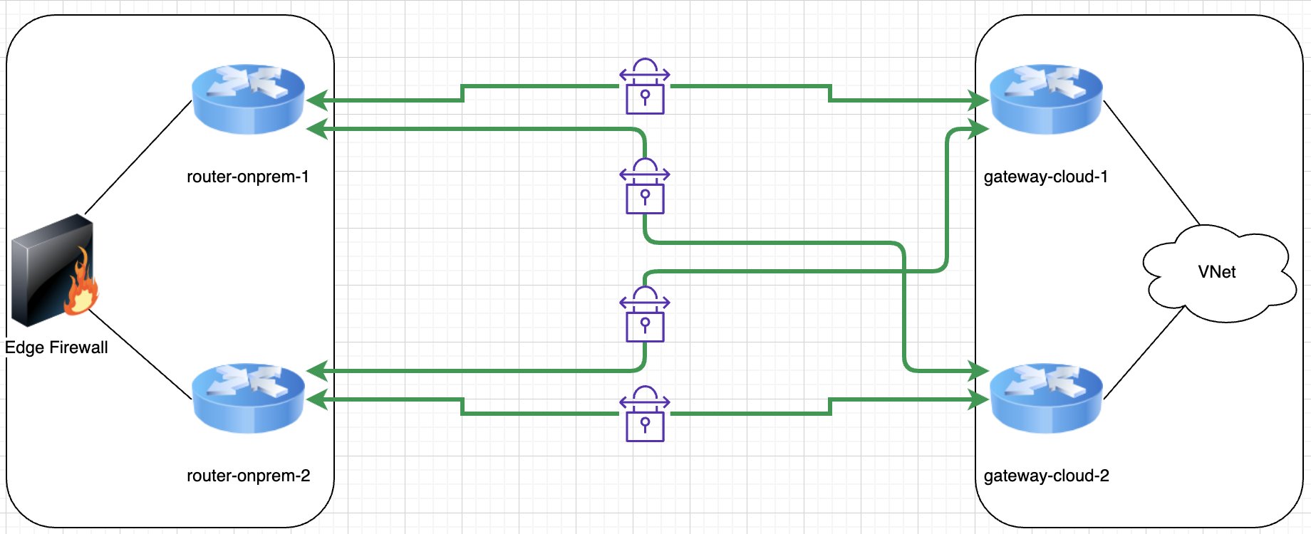
This provides four parallel tunnels and as long as one tunnel is up you can theoretically keep the services running, however how is the traffic balanced among links? that is if it’s balanced at all? What do you think is the best approach here?
Although many will have an answer for the question about the best approach, let’s be honest and admit that it depends. It depends on budget, availability, resources and skills of the team owning the setup, it depends on features available in your current equipment, etc
Active/Passive
Some teams choose to simplify their setup -or so they think- and run a redundant setup with one active link and n>0 passive links. This means all traffic travels over one link and the rest are left dormant. Dormant means different things for different teams, but in too many cases it unfortunately means not fully configured, which also implies either manual intervention or ad-hoc scripting is required to shift traffic from a failed link to another.
Another active/passive approach is at the gateway level instead of per link. This still quite common to find in many on-premises networks where e.g. asymmetric traffic is not accepted because your gateway layer is actually stateful (firewalls and such). In this approach teams will run two gateway devices with only one (the primary) handling traffic, VPN tunnels etc whilst the second just runs health checks and syncs with the primary so it is ready to take over if need be. In this approach the failover to the secondary gateway device usually happens automatically, however it usually only happens under more catastrophic failures -such as a device crash- as all services provided by the gateway have to failover.
And even though in this case where your secondary gateway device takes over automatically, there is still the potential of a communications blip meanwhile the failover happens and the tunnels are renegotiated.
Active/Active
An active/active deployment is the one where all the involved devices and tunnels are expected to be active -as in passing relevant traffic- at all times. This doesn’t only offer increased resiliency (as n number of items could be fail before the service goes down), but also increased capacity / performance / throughput in a similar fashion.
One common scenario with deployments of active/active architectures is that at some point they make a concession (due to budget, skills or just general resource constrictions) and end up having a single point of failure (SPOF) somewhere, thus reducing the overall resiliency of the service. This creates a situation where we think we are more resilient than we actually are.
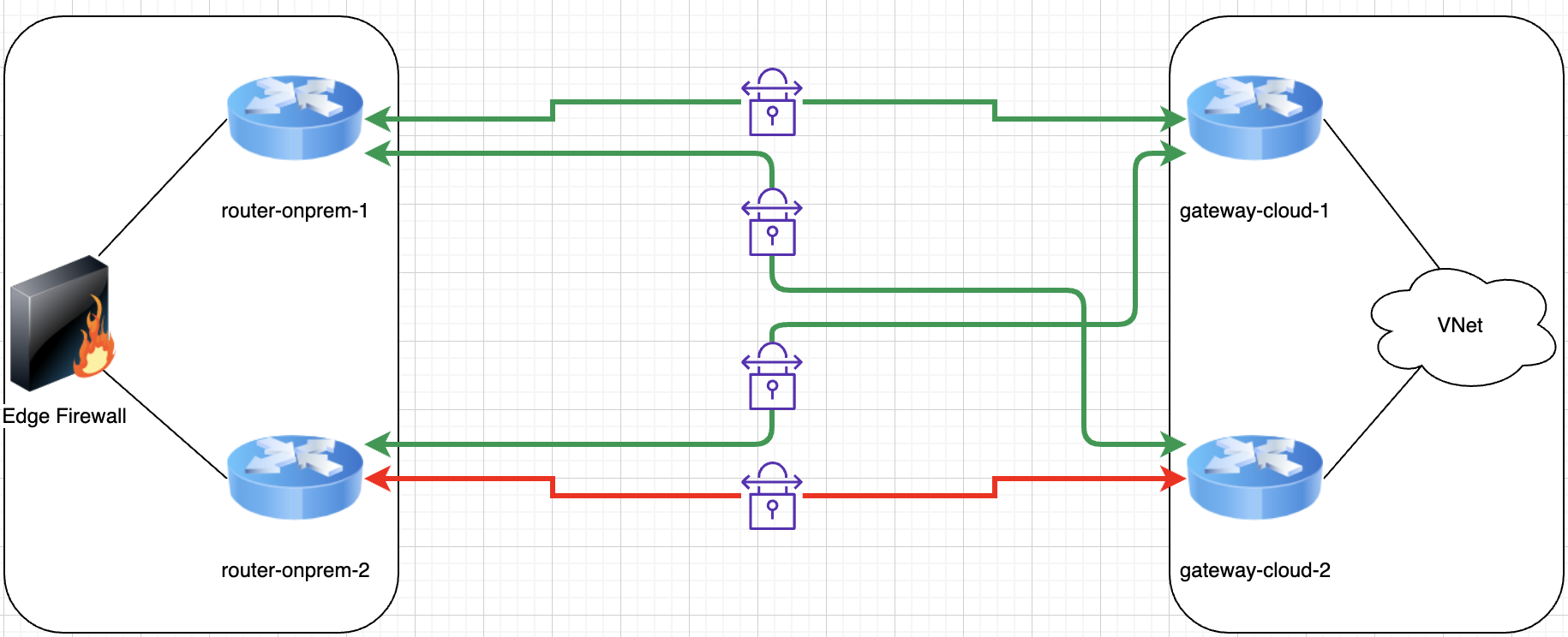
For example, a simple but effective example is in the diagram below. We see a fully redundant active/active design with 2 gateway pairs and 4 tunnels in total, but just one firewall behind it on the on-premises side:
SPOFs can be as obvious as the example above or more inconspicuous, like having important routes hardcoded as static somewhere in a mostly dynamic routing environment. You may have all the automated failover capabilities in the world, but if you have to manually change a static route to recover service then you’re SOL.
Another caveat is asymmetric routing. In a simple scenario like the above you’re going to have packets using the four available tunnels in a more or less equal way. This means the load is distributed, but it also means that packets from the same connection are going to be getting to each side over different tunnels. This doesn’t always play well with all networks, primarily due to statefulness and some anti-spoofing protections (AKA reverse-path checks).
Automated VPN failover across multiple VPN links
This capability is something you can achieve with either active/active or active/passive architectures and neither are inherently more difficult to achieve than the other, however as we’re going to rely on dynamic routing to achieve this capability you need to really know your network. Prepping for this could be used as a good excuse to update those old network diagrams and find snowflakes in your configurations such as hardcoded routes and similar quirks.
The only dynamic routing protocol -as of April 2020- I know for sure the major cloud providers support on their native VPN solutions is BGP. It may be a scary acronym for those of you not familiar with networking or that have never worked with dynamic routing protocols, but at the end of the day cloud connectivity scenarios are simple enough that you’ll end up loving BGP here.
Active/active architecture
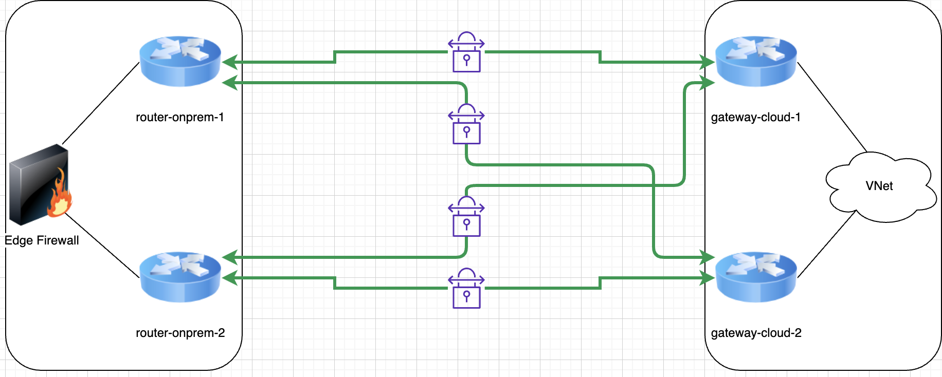
The main idea behind using BGP is to allow the remote side to advertise, over each link, what networks are reachable. This comes in very handy for automated failover and you will see why very soon. Let’s imagine the above diagram with four active VPN links between on-premises and an Azure VNet.
For this scenario you will have configured 4 BGP sessions with the remote side, as follows:
- router-onprem-1 <> gateway-cloud-1
- router-onprem-1 <> gateway-cloud-2
- router-onprem-2 <> gateway-cloud-1
- router-onprem-2 <> gateway-cloud-2
Note: A BGP session is just a conversation between two BGP peers where they announce to each other what networks can be reached through (usually, let’s keep it simple) them. BGP is a simple application over TCP (usually 179/TCP) that works like a finite machine, as follows:
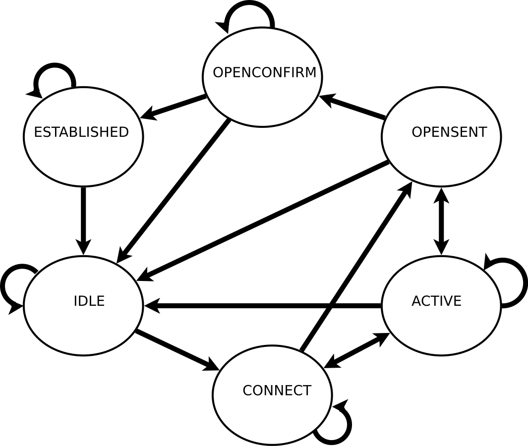
Based on the above, once the ESTABLISHED state has been achieved and we have exchanged routes, and depending on your BGP settings, the peers run a sort of keep-alive so they know the other side is still reachable and they can learn about any changes to the advertised routes. Let’s assume the keep-alive is done every 30 seconds for the sake of argument.
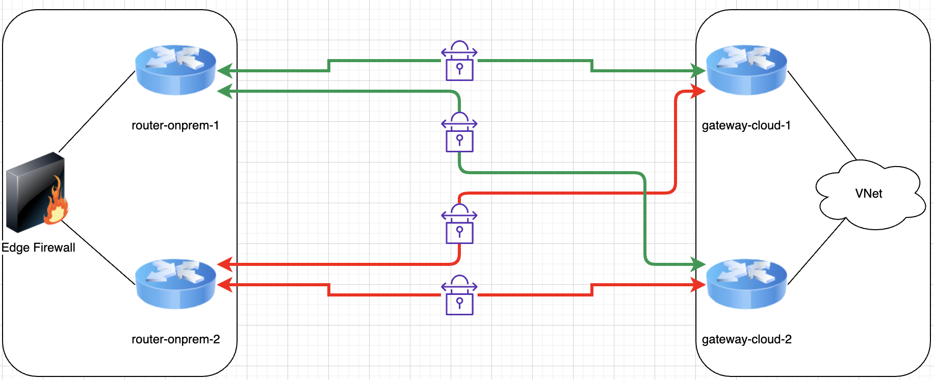
What happens then when one VPN link goes down? In 30 seconds or less each side will have tried to communicate with the other one and it will have failed. Again depending on our configuration the router may decide to already remove the routes from the forwarding table or maybe to try one or two times more to contact the remote BGP peer before removing the routes. It depends on wether you prefer a faster failover or a reduced risk of routes constantly flapping in a scenario where the VPN links are unstable or there is certain packet loss.
Automatically our side will stop forwarding traffic through one of the links:
It is important that our configuration regarding the decision of removing the routes from the routing table is the same – or very similar – on both sides. Otherwise one side may still be trying to use a broken link for a while, thus increasing our downtime without our previous knowledge. It is important that you keep downtime predictable in your recovery plans.
Most applications these days either use TCP or have built some sort of session capability over UDP, so a short time span where up to 1/4th of the packets sent could be lost may not even have a noticeable impact for users or applications as these will automatically retry any lost packets for them.
This setup is simple enough in the sense that you just need to configure four VPN links and one BGP connection over each of them. You don’t need to go deeper into BGP settings, actively monitor link health or write down processes / scripts to apply configuration changes in order to recover service. It is even simpler to configure by using infrastructure as code solutions such as Terraform!
As things stand we have achieved an active/active architecture where our traffic is balanced among 4 links and where the services that require this connectivity can keep working uninterrupted even with the loss of 50% of the routers or with 75% of the VPN links down. It is quite resilient as it would quickly auto-recover from failures such as:
- Tunnel negotiation failure.
- One router full failure.
- Two routers (one on each side) failure.
This is a great achievement for such a simple setup.
Active/passive VPN architecture
We have mentioned the possibility of an active/passive approach. Once you have seen the advantages of the active/active setup above why would we want to consider an active/passive one? Well, for one not all ISP links are created equal!
It is not uncommon for companies to have two different ISP connections on their on-premises, each one with a different provider. This increases their ability to recover service in case one of the providers has a serious issue.
The thing with these connections is that they don’t necessarily have the same bandwidth capabilities. So what if in our diagram we had our routers with two WAN interfaces, one connected to a 1Gbps line and the other connected to a 250Mbps line? In an active/active setup you would be using both lines at the same time, which under certain circumstances could cause you new problems as you may be saturating the 250Mbps line without any mechanism to correct how much traffic you put through each. You may not even know this is what’s causing you packet loss! it could become painful enough.
In this case you may prefer to use the 1Gbps line exclusively, but retain automated failover capabilities. How do you accomplish this?
BGP comes to the rescue here. Even though it is a protocol that can get complex, in this case we just need to leverage a simple parameter called AS PATH PREPEND. Each route you learn from a BGP peer comes with an attribute (amongst others) called AS PATH.
What’s an AS PATH and what’s an AS?
- An AS or Autonomous System could be considered as a routing unit / network collection. This is a loose definition on purpose as AS look very different one from another. In this case your VNet/VPC with its VPN Gateways is an Autonomous System as it advertises its own routes.
- An AS PATH associated to a route/prefix is a list of Autonomous Systems that indicates which Autonomous Systems would you have to traverse to be able to reach that prefix. Each AS is represented by either a 2-byte or a 4-byte number, known as ASN or Autonomous System Number.
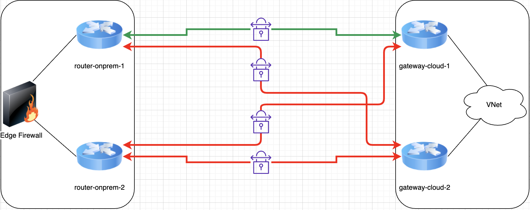
In our active/active scenario all routes learned in every BGP session (remember we have four BGP sessions) have one entry in the AS PATH, which means it is equally costly to reach a prefix through any of the VPN links. This is reflected in our routing table by showing 4 different gateways for the same route.
If we learn the same route from two different BGP sessions and in one of them there’s one entry in the AS PATH list and in the other route there are two entries in the AS PATH list, we will learn both routes, but will only put the gateway of the first route in our routing table, thus effectively using just that one link for all traffic sent to that prefix.
In our scenario we need to configure the cloud provider side to inject extra AS PATH entries for all advertised prefixes in the BGP sessions established over the 250Mbps ISP link. We can identify those BGP sessions because they are the ones associated to the VPN links that point to our routers public addresses in the 250Mbps ISP link.
This scenario -ideally- duplicates the number of tunnels and BGP sessions you have established, as follows:
- router-onprem-1 <> gateway-cloud-1 over ISP 1
- router-onprem-1 <> gateway-cloud-2 over ISP 1
- router-onprem-2 <> gateway-cloud-1 over ISP 1
- router-onprem-2 <> gateway-cloud-2 over ISP 1
- router-onprem-1 <> gateway-cloud-1 over ISP 2 (+1 AS PATH hop)
- router-onprem-1 <> gateway-cloud-2 over ISP 2 (+1 AS PATH hop)
- router-onprem-2 <> gateway-cloud-1 over ISP 2 (+1 AS PATH hop)
- router-onprem-2 <> gateway-cloud-2 over ISP 2 (+1 AS PATH hop)
This means we are forcing the cloud provider to tell us “it has an increased cost to reach me over your ISP 2 line than over your ISP 1 line”. It may be not be obvious that in order to modify how on-premises routes traffic we need to make changes on the cloud provider side, but that’s how it works! we have to influence how others route traffic to us.
So, at this point we end up with active and load balanced traffic among the four VPN tunnels over ISP 1 (1Gbps line), whilst you have already established VPN tunnels and BGP sessions over ISP 2 (250Mbps line) but not passing traffic.
In case of a catastrophic failure in ISP 1 half of your eight BGP sessions will expire, so your routing and forwarding tables will be updated immediately and traffic will automatically start flowing through the VPN tunnels established over ISP 2.
The idea here is that you keep the passive infrastructure warm instead of cold and that failover does not require human intervention or ad-hoc scripting to recover service. You have effectively accomplished fast, reliable and predictable recovery.
Again, as in other scenarios with BGP failover, the network blip depends on your decisions regarding keep-alive timers. There’s a bit more to it as there are protocols such as BFD that help you reduce considerably the recovery time whilst keeping flapping scenarios to a minimum.
Extending
In this article we have limited ourselves to a couple of routers on each side of a site to site connection, but you could extend this to multiple connections over different media such as ExpressRoute -that already leverages BGP for HA- plus redundant VPN tunnels (such as the above architectures) for failover purposes. In that case you would use AS PATH PREPEND on all the VPN tunnels so you can prioritise the use of ExpressRoute over VPN when the former is available.
Conclusion
This article showcases how easy it is to leverage scary-sounding things such as BGP to increase the reliability of our connectivity to the cloud. One should not be deterred on improving their infrastructure just because they’re not familiar or comfortable with dynamic routing protocols. This is very far from the complexity and scale ISPs -or even cloud providers- manage with their dynamic routing, however one should still be careful during the design phase to make sure no SPOFs are introduced and we can achieve the desired functionality and resiliency.